Our manufacturing standards
JUMP TO
Last updated November 20, 2022
We manufacture parts to the highest standards of quality in order to both deliver on your design vision and meet important safety and functionality requirements. To help you understand what you can expect when you order parts from Fast Radius, we’ve put together a guide of manufacturing standards across our capabilities.
This guide includes information on general workmanship standards, technical production details, and industry certifications for our Additive Manufacturing, CNC machining, injection molding, and urethane casting services.
To learn more about each of our manufacturing services, and how we make your project possible, talk to our engineering team today – or upload your CAD file to our Cloud Manufacturing Platform™.
Our standards across capabilities
We create parts for an array of industrial and commercial projects for customers across the US and the world. While every manufacturing process involves unique production challenges, we work to ensure strict safety and quality standards, and offer a range of rigorous inspection services across each of our capabilities.
Learn more about design and and quality standards across our Additive manufacturing, CNC machining, injection molding, and urethane casting manufacturing capabilities here:
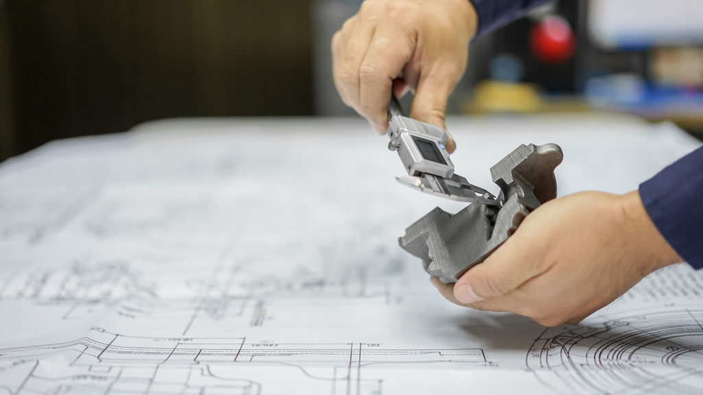
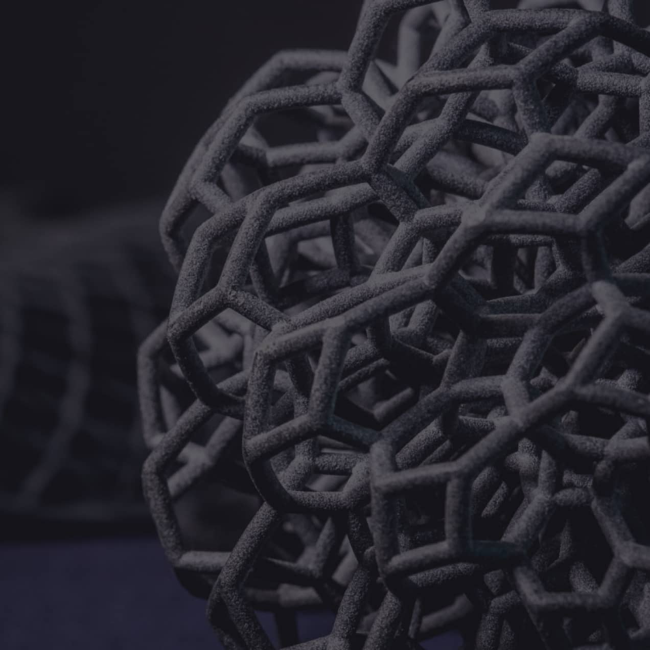
Additive manufacturing standards
Create 3D printed parts with cutting edge technologies that offer unprecedented design freedom. Our 3D printing capabilities include Carbon Digital Light Synthesis™ (DLS), HP Multi Jet Fusion (MJF), Stratasys fused deposition modeling (FDM), and Formlabs stereolithography (SLA).
To get the most out of each printing process, it’s important to understand the following design, production, and quality standards:
Learn more about our additive manufacturing capabilities
↑ top
Carbon Digital Light Synthesis™ (DLS™)
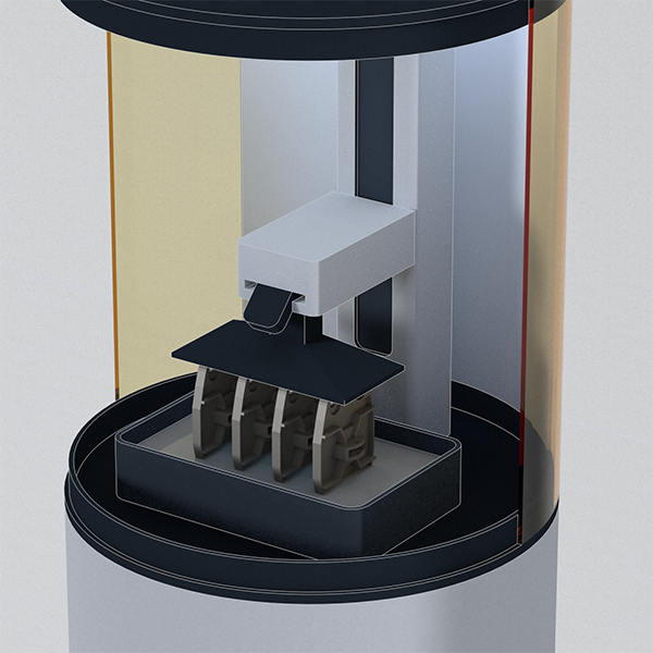
A resin-based additive manufacturing technology, ideal for creating smaller, high fidelity parts with complex geometries, isotropic properties, and excellent surface finishes. Carbon DLS™ is a photopolymerization process that projects UV light into a vat of resin material, resolving a solid part that is lifted, layer by layer, from the build area.
↑ top
Support structures
Carbon DLS™ parts that are designed with overhanging elements may require support structures to be included as part of their design. Where possible, we will manufacture your parts to reduce the need for support structures.
- In general, angles greater than 45 degrees relative to the build plane are self-supporting and do not require external support.
- By default, Fast Radius will use sanding tools to remove support nubs from parts. Areas with sanded support nubs may have a different texture and color than areas without sanded support nubs.
Warping
Some DLS™ printed parts may warp as a result of sintering/thermal contraction. We will work to reduce and, where possible, eliminate the effects of warping during design and production.
As with other manufacturing processes, uniform wall thicknesses and smaller aspect ratios will help to alleviate warpage
Build area
DLS™ projects are limited by the size of the printer’s build volume. Our engineers will work with you during the design process to ensure your parts are optimized for build volume.
Surface finishes
The DLS™ printing process may show fine layer lines on finished parts. Where possible, we will work to reduce layer lines during the design process and recommend post-processing options to enhance the appearance of your parts.
- “As printed” surface finishes on rigid parts may have visible striations/layer-lines, but have a glossy, smooth finish.
- “As printed” elastomeric parts generally show less striations/layer lines and have a matte finish.
- Parts with sanded support nubs will have a slightly smoother and matte surface finish with slight color differences.
↑ top
Carbon Digital Light Synthesis™ production standards
| Build volume | M2 printer • 189 x 118 x 326 mm • 7.4 x 4.6 x 12.8 in L1 printer • 400 x 250 x 460 mm • 15.7 x 9.8 x 18.1 in | |
| Minimum feature size | Material dependent, typically: • ~0.25 – 0.5 mm • ~0.01 – 0.02 in | |
| Standard tolerance | Material dependent, for rigid materials typically: (0-100mm feature size): • +/- 0.3 mm • +/- 0.012 in (>100mm feature size): • +/- 0.3% of feature size |
↑ top
Support structures
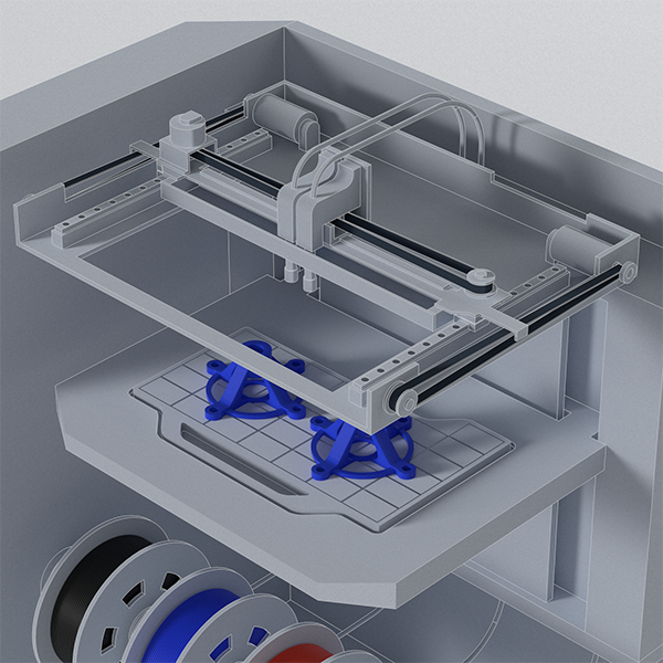
Stratasys FDM parts that are designed with overhanging elements may require support structures to be included as part of their design. Where possible, we will design your parts to reduce the need for support structures.
• In general, angles greater than 45 degrees relative to the build plane are self-supporting, and do not require external support.
• We use both breakaway supports which are removed by hand/tool, and soluble supports.
• Breakaway supports:
· PC-ISO
· PC-10
· Ultem 1010
· Ultem 9085
· PPSF
· Antero800NA
· Antero840CN03
• Soluble supports:
· ABS-M30
· ABS-M30i
· ABS-ESD7
· ASA
· Nylon 12
· Nylon 12 CF
· Nylon 6
· PC-ABS
· PC-10
• Specialty supports
· ST130 (soluble)
Warping
Some FDM printed parts may warp and lift from the print bed as a result of thermal cooling. We will work to reduce and, where possible, eliminate the effects of warping during design and production.
We may advise the following mitigation strategies to address and prevent warping:
• Anchor pins
• Specific build orientation
• Material choice: nylon and Hi Temp materials, for example, are more susceptible.
• Adjustment to the radii of interior corners
• Support ribs
Build area
FDM projects have a build area of 36x24x36”. Our engineers will work with you during the design process to ensure your parts are optimized for their printer’s build area.
Corners
FDM printers use a circular nozzle, meaning that corners and edges are never perfectly square.
- It may be difficult to achieve modeled threads of precision features during the FDM print. We recommended using taping or threaded inserts.
- Lowest available contour setting for FDM prints is 0.0080”.
Surface finishes
The FDM printing process leaves layer lines on finished parts.
- We will sand layer lines on reachable surfaces – sanding works best with 0.007” or 0.005” layer height.
- Breakaway support structures may leave slight imperfections.
↑ top
FDM production standards
| Build volume | · 914 x 610 x 914 mm · 36.0 x 24.0 x 36.0 in |
| Minimum feature size | · 0.4 mm · 0.016 in |
| Standard tolerance | · ± 0.381 mm · 0.015 in |
↑ top
Warping
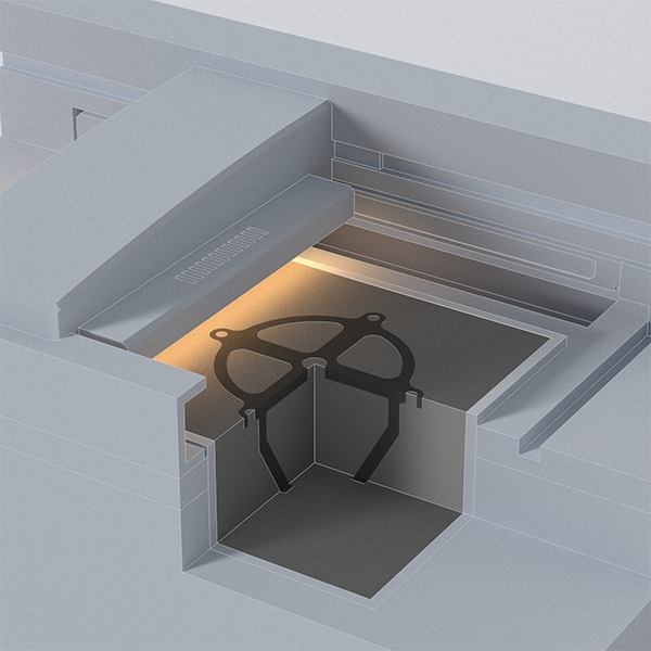
Some MJF printed parts may warp as a result of thermal effects during the printing and cooling processes. We will work to reduce and, where possible, eliminate the effects of warping during design and production.
As with other manufacturing processes, uniform wall thicknesses and smaller aspect ratios will help to alleviate warpage.
Build area
MJF projects are limited by the size of the printer’s build volume. The build volumes are listed in the table below.
Surface detail
HP MJF printed parts have a natural, matte gray, consistent surface finish. Areas on a part facing upwards in a build are more likely to show fine layer lines.
HP MJF parts may be black dyed to achieve an even-colored finish.
Surface finish
Though MJF parts are nearly fully isotropic, fine layer lines may be visible on certain areas of parts.
Fast Radius performs comprehensive quality checks on parts to identify and eliminate common manufacturing defects.
↑ top
HP MJF production standards
| Build volume | HP MJF 4200/5200 · 375 x 375 x 280 mm · 14.8 x 14.8 x 11.0 in HP MJF Color · 332 x 190 x 248 mm · 13.1 x 7.5 x 9.8 in | |
| Minimum feature size | HP MJF 4200/5200 · 0.5 mm · 0.02 in HP MJF Color · 0.5 mm · 0.02 in | |
| Standard tolerance | HP MJF 4200/5200 Features in X-Y Dimension (0-100mm feature size): · +/- 0.3 mm · +/- 0.012 in Features in X-Y Dimension (>100mm feature size): · +/- 0.3% of feature size Features in Z Dimension (0-100mm feature size): · +/- 0.4 mm · +/- 0.016 in Features in Z Dimension (>100mm feature size): · +/- 0.4% of feature size HP MJF Color Features in X-Y dimension · +/- 0.4 mm · +/- 0.016 in Features in Z dimension · +/- 0.8 mm · +/- 0.031 in |
↑ top
Stereolithography (SLA) standards
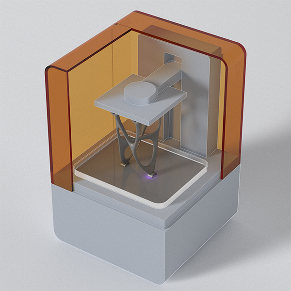
A tried-and-tested prototype manufacturing process, SLA is capable of producing parts with intricate, accurate detailing, and excellent surface finishes. SLA is a photopolymerization printing process that involves the application of a UV laser to layer upon layer of liquid resin in order to resolve solid parts.
↑ top
Support structures
SLA printed parts that are designed with overhanging elements may require support structures to be included as part of their design. Where possible, we will design 3D printed parts to reduce the need for support structures.
• In general, angles greater than 45 degrees relative to the build plane are self-supporting, and do not require external supports.
• By default, Fast Radius will use sanding tools to remove support nubs from parts. Areas with sanded support nubs may have a different texture and color than areas without sanded support nubs.
Warping
Some SLA printed parts may warp as a result of thermal contraction during the cooling process. We will work to reduce and, where possible, eliminate the effects of warping during design and production.
As with other manufacturing processes, uniform wall thicknesses and smaller aspect ratios will help to alleviate warpage
Build area
SLA projects are limited by the size of the printer’s build volume. The build volume is listed in the table below.
Surface detail
The SLA process can achieve very fine surface finishes with smooth textures. Layer lines in the SLA process are less prominent than other additive processes.
Cleaning
SLA parts are washed in an isopropyl alcohol rinse tank post-print, then swabbed by-hand to remove any trapped excess resin. After rinsing, the parts enter a UV curing oven to establish final material properties.
Surface finish
Fine layer lines may be observed on certain part geometries. SLA parts have a naturally smooth finish and supported areas are sanded down by default.
↑ top
SLA production standards
| Build volume | • 335 x 200 x 300 mm • 13.2 x 7.9 x 11.8 in | |
| Minimum feature size | Minimum feature size is different for each resin – we are able to achieve complex and aggressive geometry. | |
| Standard tolerances | Material dependent, for rigid materials typically: (0-100mm feature size): • +/- 0.3 mm • +/- 0.012 in (>100mm feature size): • +/- 0.3% of feature size |
↑ top
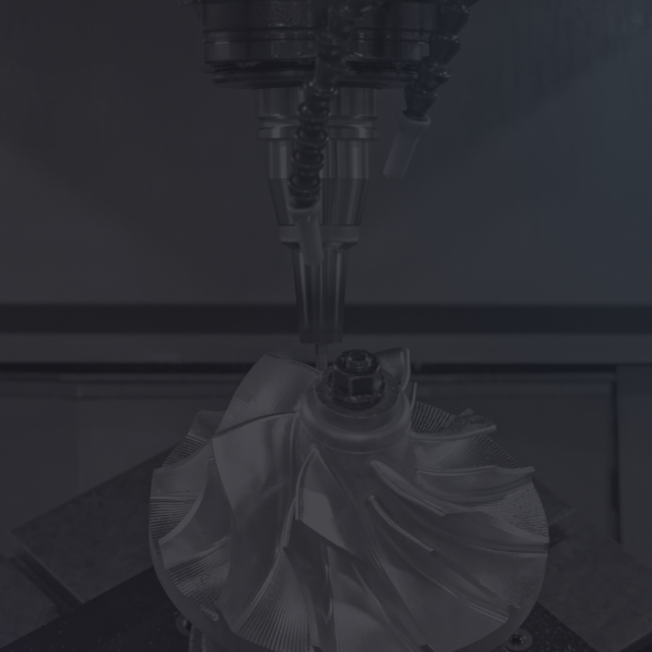
CNC machining standards
Manufacture high quality metal and plastic parts, from low volume prototypes to high volume mass production, with computer-controlled precision. Our CNC milling and turning processes utilize the latest manufacturing technologies and machine tools to make your parts with the highest quality and efficiency. Explore our CNC machining design, production, and quality standards here:
↑ top
Sharp edges
All sharp edges will be broken to .01” max. All parts are fully deburred as standard.
Sharp edges are available on request.
Surface finishes
• Default surface finish for CNC parts is As-machined (broken edges).
• Standard surface roughness is 125 Ra. Finer finishes are available upon request
Certifications
ISO 9001:2015 and AS9100D
Tolerances
Unless otherwise specified, parts are machined according to ISO 2768mk
↑ top
CNC milling standards
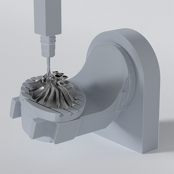
CNC milling is a computer-controlled, subtractive machining process that uses rotating cutting tools to remove material from a solid, stationary workpiece in order to create custom parts. The workpiece is cut along a number of axes to achieve a variety of shapes and geometries.
↑ top
CNC milling general process information
| Maximum part size | 3-axis milling · 1800 x 1000 x 500 mm · 70.9 x 39.4 x 19.7 in 5-axis milling · 1000 x 900 x 600 mm · 39.4 x 35.4 x 23.6 in | |
| Minimum part size | 3-axis milling · 12.7 x 12.7 x 12.7 mm · 0.25 x 0.25 x 0.25 in 5-axis milling · 12.7 x 12.7 x 12.7 mm · 0.25 x 0.25 x 0.25 in | |
| Minimum feature size | 3-axis milling · Ø 0.1 mm · Ø 0.004 in 5-axis milling · Ø 0.1 mm · Ø 0.004 in | |
| Standard tolerance | For Metals features of size (Length, width, height, diameter) and location (position, concentricity, symmetry) +/-0.005 in / +/-0.13 mm following ISO 2768 unless otherwise specified For Plastics features of size (Length, width, height, diameter) and location (position, concentricity, symmetry) +/-0.008 in / +/-0.20 mm following ISO 2768 unless otherwise specified | |
| Minimum wall thickness | · Recommended size: 0.8 mm (0.031 in) for metals and 1.5 mm (0.059 in) for plastics · Feasible size: 0.5 mm (0.019 in) for metals and 1.0 mm (0.039 in) for plastics | |
| Holes | Recommended size: · Diameter: Ø 1.0 mm (0.040 in) or larger · Depth: 6 x diameter Feasible size: · Diameter: Ø 0.25 mm (0.010 in) · Depth: 12 x diameter | |
| Threads | Recommended size: · Size: M1 or larger, 0-80 or larger | |
| Internal edges | Recommended size: R 1 mm (0.040 in) Feasible size: R 0.25 mm (0.010 in) | |
| Lead time | 3-axis milling · As low as 3 days for less than 50 parts 5-axis milling · As low as 6 days for less than 50 parts |
↑ top
CNC turning standards
CNC turning involves the use of a lathe and stationary cutting tool(s) to machine a rotating blank workpiece. Turning is a precise and scalable machining operation suitable for cylindrical parts with round cross-sections.
| Maximum part size | · Ø 760 mm · Ø 30 in Larger diameters may be feasible at shorter lengths. |
| Minimum part size | · Ø6.0 mm · Ø0.25 in |
| Minimum feature size | · Ø 0. 1 mm · Ø 0.004 in |
| Standard tolerance | For Metals features of size (Length, width, height, diameter) and location (position, concentricity, symmetry) +/-0.005 in / +/-0.13 mm following ISO 2768 unless otherwise specified For Plastics features of size (Length, width, height, diameter) and location (position, concentricity, symmetry) +/-0.008 in / +/-0.20 mm following ISO 2768 unless otherwise specified |
| Minimum wall thickness | · Recommended size: 0.8 mm (0.031 in) for metals and 1.5 mm (0.059 in) for plastics · Feasible size: 0.5 mm (0.019 in) for metals and 1.0 mm (0.039 in) for plastics |
| Holes | Recommended size: · Diameter: Ø 1.0 mm (0.040 in) or larger · Depth: 6 x diameter Feasible size: · Diameter: Ø 0.25 mm (0.010 in) · Depth: 12 x diameter |
| Threads | Recommended size: · Size: M1 or larger, 0-80 or larger |
| Internal edges | · Recommended size: R 1 mm (0.040 in) · Feasible size: R 0.25 mm (0.0109 in) |
| Lead time | As low as 3 days for less than 50 parts |
↑ top
Injection molding standards
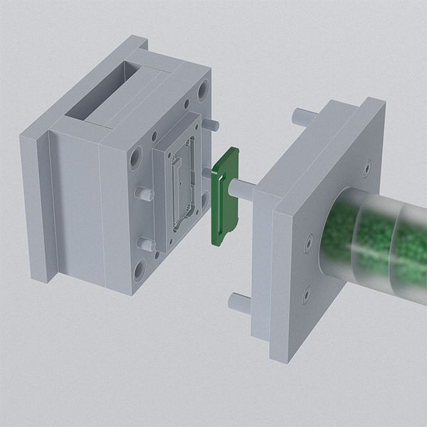
Injection molding involves the injection of molten thermoplastic into a metal mold, which is then cooled to form a solid part. The process is best suited to high volume production requirements and is capable of creating strong, cost-effective parts with precision and consistency. Injection molding projects involve the following production, design, and quality standards.
↑ top
Part tolerances
Standard: +/-0.005”
Best achievable: +/-0.001”
For larger part tolerances please contact a Fast Radius engineer
Maximum part weight
350oz
Finishing standards
Vary by supplier capabilities. Our finishing standards include:
- SPI
- VDI
- Mold-tech
- Brazil
Mold gates
Gate locations will be chosen by tool suppliers and verified with customers by default, though customers can request their preference if the location is critical.
Regrind
Maximum allowable regrind percentages are set by our molding facilities. Some facilities limit maximum allowable regrind due to dust and process variability.
Certifications
Relevant certifications are specific to the industry for which parts are being made. We can provide material certifications to many international standards by explicit request from the customer. Examples include:
- TSF
- AS9100
- ISO 13485
- Class 7 and 8 clean rooms
↑ top
Injection molding general process information
| Maximum part size | • 1500 x 1400 x 750 mm • 59 x 55 x 29.5in | |
| Minimum part size | • 1 x 1 x 1 mm • 0.04 x 0.04 x 0.04 in | |
| Lead time | • As low as 2 weeks for T1 samples • After T1 sample approval, lead time for < 10,000 parts is as low as 1 week | |
| Tool validation | Standard process is to produce a small set of T1 samples for approval before initiating full production | |
| Maximum press size | 1600T | |
| Minimum order size | 100 parts and $5000 | |
| Set-up fee | Typically $500 per mold per order (applies to sample runs after initial T1 samples or engineering changes) |
↑ top
Urethane casting standards
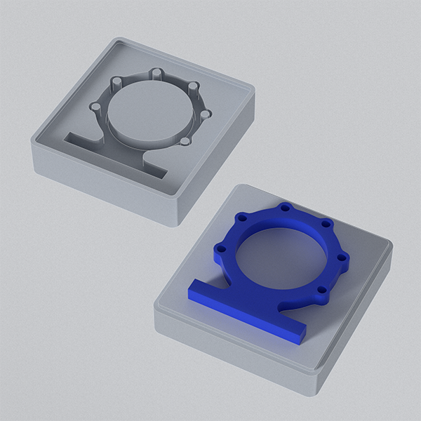
Urethane casting enables the manufacture of replicas of master parts with high precision and efficiency. During the casting process, urethane resin or silicone is poured into a mold, heated in a vacuum chamber, and then left to cure. The urethane casting process is best suited to low to mid-volume production, offering faster turnaround times than injection molding and a tooling process as low as two weeks.
↑ top
Part consistency
- +/-0.005 first inch (+/-0.010″ first inch for big parts)
- +/- 0.003″ for additional inches
There may be slight variation between cast urethane parts due to the nature of producing parts out of flexible molds.
Soft tooling may also cause aesthetic variations which can be improved with post-processing procedures.
Part geometry
The appearance of drafts, undercuts, sharp edges, and corners will be dependent on part geometry.
Part lines
Part lines may be visible on cast urethane parts depending on geometry.
Support ribs
Parts may require support ribs depending on geometry.
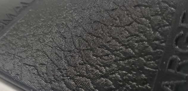
Surface finishes
We are capable of achieving matte, smooth, and satin part finishes. We are also capable of gloss and polished finishes, and Mold-tech textures.
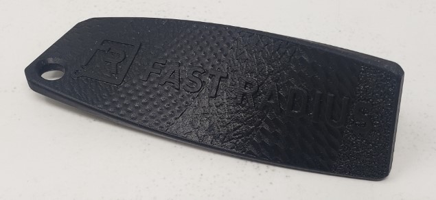
Letters and logos
We are capable of casting logos and letters at a minimum of 0.025”. Recessing letters allows the operator to finish around them.
Positive letters will enable us to apply finishes, and build lines will be visible on the final product.
Bosses
We are capable of designing parts with bosses to accommodate threaded inserts if required.
Certifications
We manufacture parts to ISO 9001 standards.
↑ top
Urethane casting general process information
| Maximum part size | • 914.4 x 914.4 x 1828.8 mm • 36.0 x 36.0 x 72.0 in • Note: Ability to break parts up into multiple segments to create an even larger assembly |
| Minimum feature size | • 0.635 mm for features • 0.025 in for features • 1.016 mm wall thickness • 0.040 in wall thickness |
| Standard tolerance | • 0.005 in (0.127 mm) for first inch, followed by 0.003 in (0.0762 mm) per lineal inch cumulatively |
| Lead time | •As low as 7 days for first articles (FA) • After FA approval, as low as 1 week for remaining parts |
↑ top
Changelog
Keep up with changes to our production, quality and design standards with our tracked changelog
November 21, 2022
Manufacturing Quality Standards page published.
↑ top
Fast Radius manufacturing capabilities
Fast Radius manufacturing solutions serve the needs of businesses across the industrial landscape. Explore our capabilities:
Get a quote for your parts today
Create a Fast Radius account for rapid quotes on your manufacturing projects.